So I decided to try something new, and downloaded the latest and greatest AVR Studio 5. Downloaded installed and created a new AVR C executable project, it asked for device, I told it and it made happy :).
As with anything it's hard to know where to start, so I just started playing around and found IO view. First thing you'll want to do is Debug~>Options and Settings~>Text editor~>All Languages and check-mark line numbers. Yea I'm a noob and need line numbers. So I dropped in a simple blinky light, BUT I dropped one in from another chip. It was polite and let me know that certain ports were not defined, helped me correct it, compiled it to a hex file, ready for AVRDude to put it on the chip.
So I've downloaded and installed AVRStudio5 put in an incorrect program, built it, put it on a chip and had it work. It has a lot of tools that I don't yet fully understand, but I think I'll figure them out. But that... is another post.
Yes, I'm talking about sending data from an AVR chip to a USB port. I've been wanting to do this for awhile, to be able to log data over a time period, and creating custom interfaces for random... ok fine I don't have any damn good reason other than I just want to know how it works. I've been taking stuff apart for years to find out, now I'm putting things together to find out how it works. Regardless. Hackaday ran this I figured it's a good start, but I don't just want to keep repeating stuff everyone else does. BUT I figure I need a breakout board. Some sort of interface between the two.
Vcc pin goes to Vcc on the chip, and GND to the GND pins
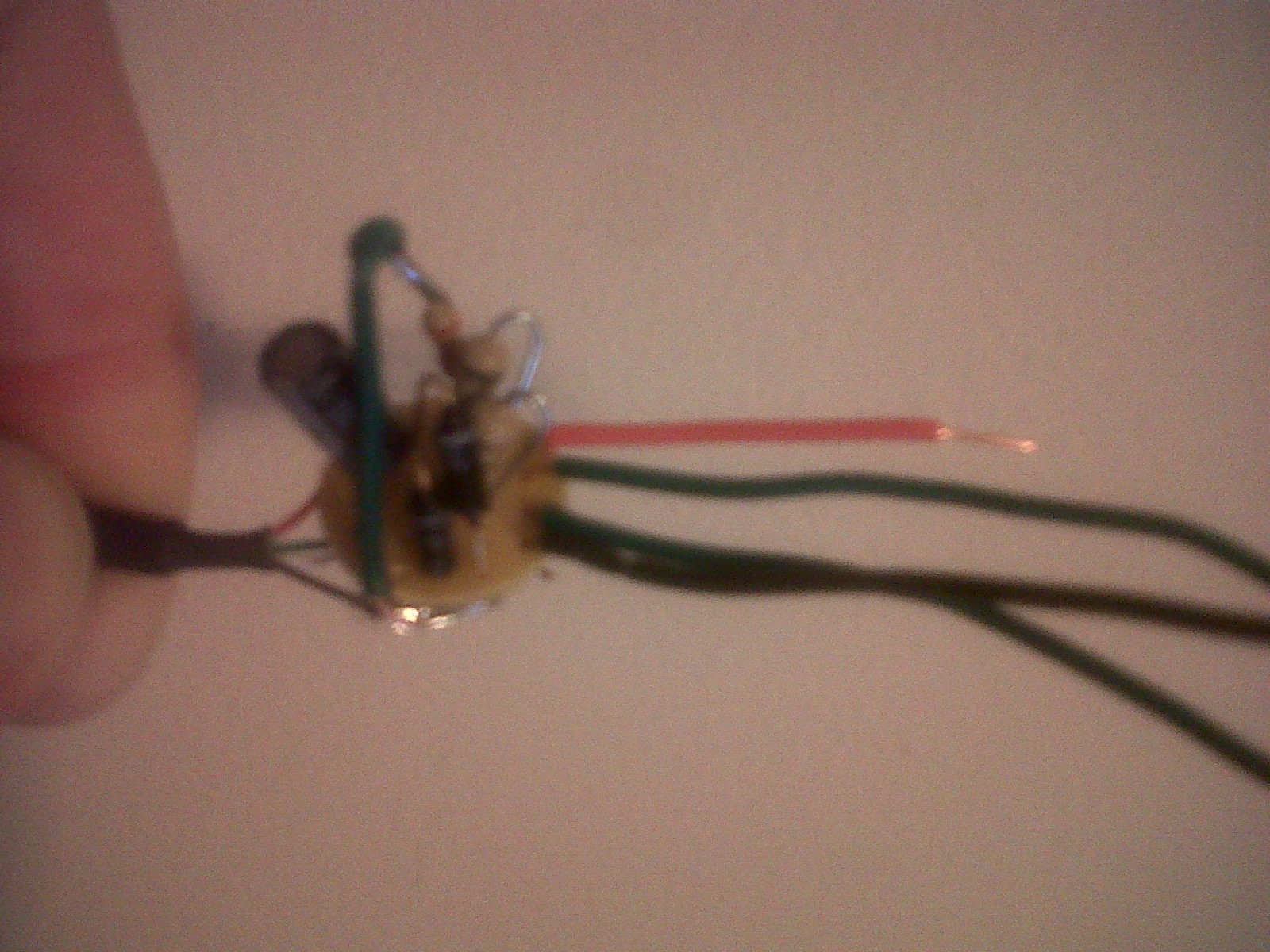
Seems pretty simple, and it is. The Diodes are used as a cheap voltage regulator. That way the chip outputs 5v and the diode regulates it down to 3.6v to go into your USB port on your computer. (not something you want to burn out) The 100uF is probably just decoupling he put a 100nF on the chip between Vcc and ground, probably for the same reason. R1 and R2 feed the data pins on the chip. Simple yes? In my infinite wisdom I for some reason chose the smallest protoboard I had XD So things got tight, not the most elegant solution, but it should work. I outputted everything to wires so I could breadbord it how I wanted with little problem. Now I just have make the chip work!
So the wife and I throw a party every fall around Halloween, and we theme it. This year's theme was Time Travel, and I had intended to go as the time traveler from H.G.Well's book 'The Time Machine'. Well best laid plans of mice and men and all that, I was convinced to appear as Dr Who. Intrigued by the brilliantly geeky suggestion by someone who didn't even show up, I accepted the challenge. I don't have a Police Box. Neither do I have the time (given the amount of housework, homework, and... well, work I have at the moment) to build one. But the Doctor without a TARDIS is like being a vampire without teeth. Just ties the whole thing together. My origonial intent was to program a 'breather' on an ATTINY13, add power and enjoy the pulsing light of a TARDIS light atop my shed. I had a problem getting the program to do what I wanted it to, and then... for some reason (after I had several glasses of wine) I couldn't program the chip. (PROTIP: AVRDUDE cannot program a 555 timer). From nowhere I got a brilliant idea! I had found a spare 555 timer I had mislaid some time ago, I could use it! Next day at radioshack, I picked up one of these bad boys and figured I could use one of these too. I put the 555 in AStable mode the circuit looks something like this.
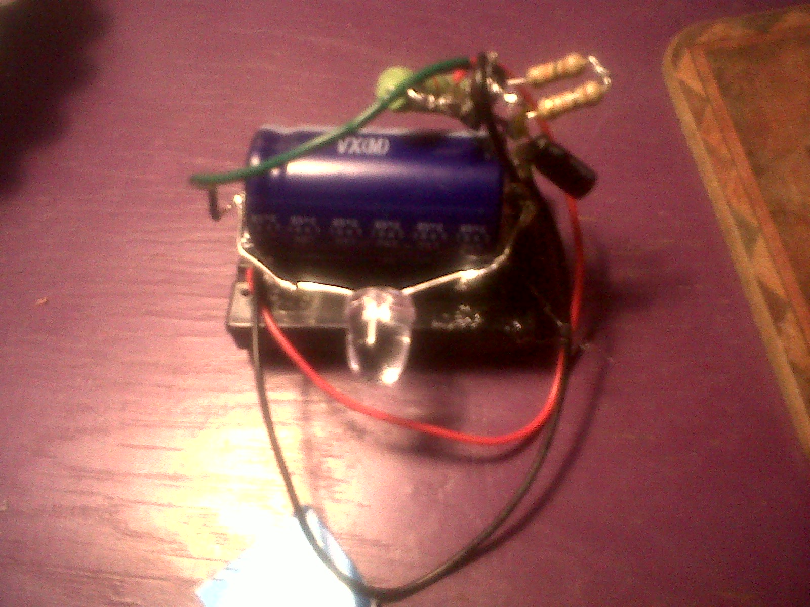
R1 is 1k, R2 (as you can see form the pics) is actually 2 10k in series. C is 100μF. So everything can be found at Radioshack. (and was). So your asking where the LED is... pin 3 outputs the signal, a 330 ohm resistor feeds the LED and the 4700μF inline cap that are connected in parallel. Caps don't like sudden changes in voltage, so when pin3 goes high, the cap robs some of the sudden voltage, and the effect is a slow turn on of the LED. the process is reversed when Pin3 is suddenly turned low. The Cap feels bad about having all the voltage, and lets it loose. The effect is a slow turnoff. It also makes people nervous to see a giant capacitor. Addmittedly its completly unneccessairy to have a 35V cap for a 5v chip... but that's whats at the shack. Actually there is only 4.5V, I used 3AAA batteries, it ran all evening with no probs. I was quite happy. Here's the effect while it was still on the Breadboard. By this point I had several stiff drinks, so instead of using the protoboard to solder on I deadbugged it... it's a miracle it works but it does.
I've not been around for a bit, so I thought I would drop in some posts as to what I've been up to. As for the HAL project, HAL isn't up and running, I blew the 3.3v regulator on the Bus Pirate at some point when I was updating it to version 4.1. Undaunted I tried something else. I decided I needed to slip into a shallower end of the pool, and ordered 10 attiny13s. Yes ten. I found some good 'make the light flash' hex file and set about to dropping it into the chip. I also ordered (from my friends at Sparkfun) the pocket AVR programmer. I plugged the programmer into the computer, plugged the chip into the programmer and SHZAM! it worked! Yea right.
The System is based around a series of programs called AVR Dude. And simply installing AVR Dude isn't enough. What I did was I installed the newest version of WinAVR (comes with AVR Dude, as well as programmer's notepad) now this is all command line stuff at this point, and requires the ability to use a makefile. I'm no Guru and there are most definitely more elegant ways to get the job done, but here's the pudding.
I make the light blink!
So that's the uC version of hello world. remember your 330k resistor. The chip is one of the attiny13s and FYI I had to define my usb port weird, 'avrdude -c usbtiny -p attiny13 -P #port_#0001.Hub_#005 -U flash:w:test1.hex' I would do a post as to how exactly I got it to work, but honestly I'm not bloody sure.
 So I decided to try something new, and downloaded the latest and greatest AVR Studio 5. Downloaded installed and created a new AVR C executable project, it asked for device, I told it and it made happy :).